
The construction of a house with a total area of 155 m2 according to the technology that allows you to significantly reduce the total expenditure.
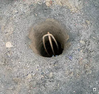
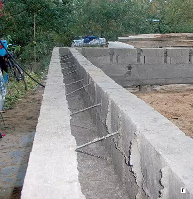
A- in the well placed fittings;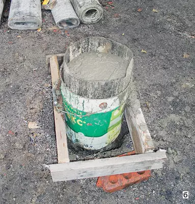
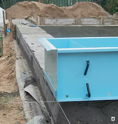
A- stretch the cord;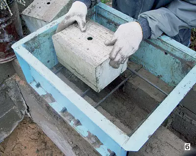
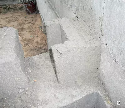
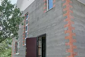
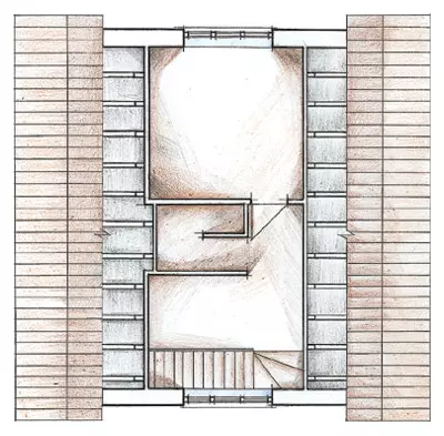
The openings were separated by brickwork;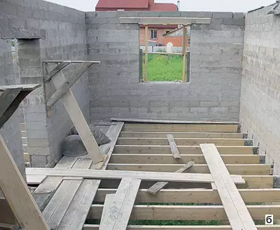
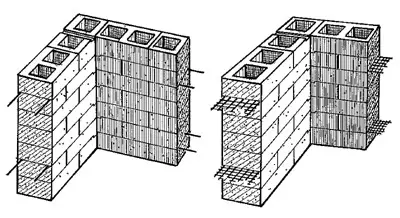
ATISE-2M differ with a jumper;
The cost of building a house is consumed from the costs of building materials, labor and equipment. TISE technology that implies construction without the use of heavy lifting vehicles, based on cheap materials, can significantly reduce the total expenditure.
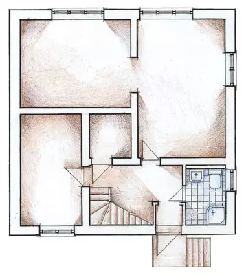
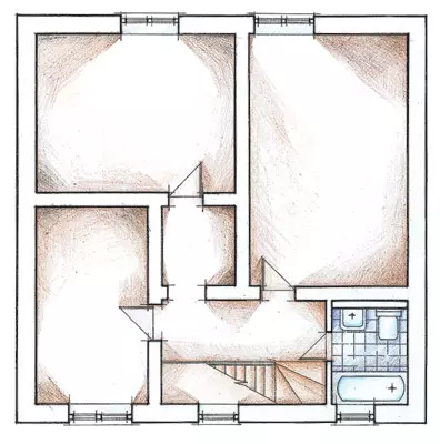
Project "Hope"
The sequence of actions during the construction of a two-story cottage according to the TISE technology covering the construction of the foundation and walls of the building, we will consider on the example of the standard Nadezhda project. The house is designed for year-round family accommodation from 4-6 people. Building area - 81m2, total area - 155m2, residential - 75.7 m2. The cottage was built by a brigade of four people, the time of work- 2.5 months.Basic tab
Before the start of work, the soil was analyzed and the type was determined, since it depends on the choice of the foundation type. The soil on the site was bubbling, so the foundation began to build a columnar-belt. The design is formed from the supports shrouded below the level of the freezing, and the overhead part of the woodwork.
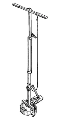
When creating a columnar-ribbon foundation, a manual foundation "TISE-F" was used (the price of 1500 rubles) to perform supporting wells with an extended cavity at the bottom. Actions were made by two workers, which made it possible to significantly reduce the cost of this construction phase.
The construction of the foundation began with drilling wells under support. After that, (every time it took about an hour) in it turned into a pre-prepared fittings, made in the form of two U-shaped brackets made of reinforcement steel with a diameter of 12mm, located crosswise. Each bracket was made of a rod of the armature with a length of 3m at the calculation so that the finished carcass spoke from the well to 15-20 cm.
Pillows from sand or gravel when building a column foundation of this type are not created!
Then they started filling the well concrete of the following composition in bulk parts (cement-sand-crusp, water): 1: 3: 2: 0.7. At the same time, the cement brand M400 was used, crushed stone-granite, because porous materials (brick, lime crushed stone, ceramzit, IT slag) significantly reduce the frost resistance of the foundation pillar, which can later lead the design to the emergency condition.
Before filling in concrete, each well was installed pegs-pointers of the level of the lower edge of the ribbon frame. Moreover, the minimum gap between the soil and painter should be 15cm (it is necessary for the subsequent shrinkage of the house). The concrete was laid with layers of 15-20 cm and compressed careful plump. The concrete mixture itself was prepared for no more than an hour of work and implemented until the setting.
Supports foundation
To determine the number and size of the foundation pillars, the steps of their installation carried out the calculation, in which the carrying capacity of the soil, the weight of the house with the operational load and the weight distribution under the carrier walls was taken into account. To determine the depth of the foundation of the foundation pillars, it is necessary to know the depth of the soil freezing in this area (for Moscow- 140cm), the type of soil, the level of ground and flood waters and their seasonal changes.
Guided by the results of the calculations, the following support characteristics were adopted: the extension diameter of the lower part 0.6m, the total depth of drilling - 1.6 m, the installation step is 1.5m. Supports should be located at the corners of the house, around the perimeter and under the inner carrier walls of the first floor with a specified step (1.5 m). In this case, the 24 posts were placed on the perimeter of the house, under the inner walls - 20 pillars, that is, it took only 44 columns to create an underground part of the foundation.
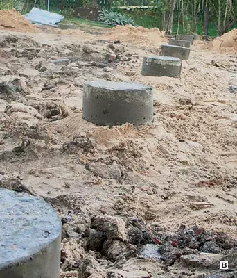
After filling in the bottom of the bottom of the well (5-10 cm above the expansion), it was brought into it rolled into the tube a pergamine shirt that formed a smooth part of the well. The length of the workpiece of the shirt (1.8m) was taken at the rate of which it will perform from a well 15-20 cm under the upper edge of the clogged position-level pointer. Then completed the filling of the well concrete under the top crop of the shirt.
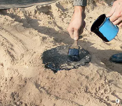
The next day, the protruding ends of the supports were covered with bitumen (so that the water from the supports did not succeed in the woodlock and walls). The process of creating one post, taking into account the drilling time, the well lasted about one and a half hours; For all 44 supports left a week. When the last support was completed, they began to organize the horizontal dressing of the frame-woodscript.
The formwork for the scarlet with a height of 40cm and 35cm width was performed from the boards. (In general, the width of the screening tape is determined by the width of the walls of the wall and the type of base.) To simplify the creation of formwork on the perimeter of the house, they made technological dumping from the sand under the edge of the foundation columns, seal it and covered with a pergamine. Together, the arrangements of the ends of the supports in the pergamine cut the holes under them. Renta-Scarret was reinforced by a rod with a diameter of 12mm- four from below and on top to the cross section of the tape, but not closer to 3 cm from the edge. To do this, the layer of concrete was poured into the formwork with a thickness of approximately 4 cm and laid the lower rods on it. Next, the formwork was filled with concrete, not reaching 4cm to the top, and immediately laid the top rods, after which the concrete was fulfilled to the end. The relationship between the headscaling and supports appears only after the complete fill of concrete into the formwork: Under the weight of the concrete, the dumping sends to about 1 cm, so that the supports penetrate the foundation tape. The surface of the tape (after the start of solidification) was carefully smoothed and controlled the level of uneven framework to make the masonry is unacceptable.
Rent was moistened for a week. The platform was performed after 7 days, after which they removed the technological dump. Thus, they created a gap between the headscaling and the soil, compensating the bunched phenomena. The opinion that when building such a columnar-ribbon foundation, the gap should be filled, is a gross mistake. Violation of this rule will result in the soil, extinguishing, simply pulling the ribbon from the supports.
We give the volume of materials used for the construction of the foundation. The volume of concrete required for the supports and tape is 13m3. The total consumption of materials on the foundation device: cement - 3.5 tons, sand-6m3, crushed stone - 6m3, reinforcement 12mm- 480kg, pergamine-100m2.
At the prices of the mid 2005. (Moscow) The cost of materials was about 25 thousand rubles. The total time of the construction of the foundation is 10 days.
Concrete strength has already allowed the day after the framework of the screaming to start the construction of walls according to TISE technology.
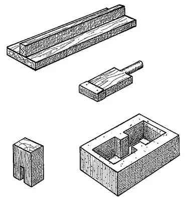
TISE modules
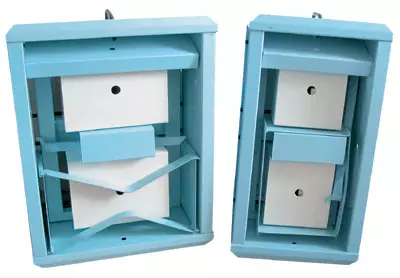
All components of the module are made of steel. If it is properly operation, it is possible to define up to 10 thousand wall blocks, the dimensions of which are multiple by the usual two-row masonry "in the brick" (for tees-2m) or "one and a half of the brick" (for tees-3m). This allows combining such walls with traditional construction materials.
The module is available in two main modifications that allow you to create blocks of the following dimensions (DHS):
Tees-2m- 510150250mm (mass-14kg);
Tees-3m- 510150380mm (mass-18kg).
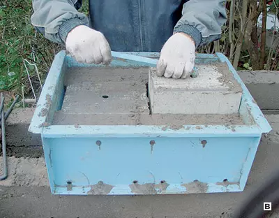
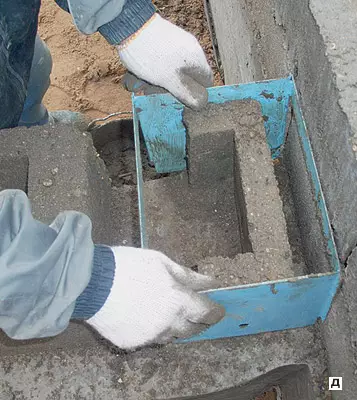
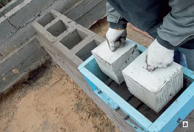
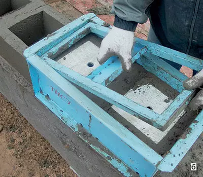
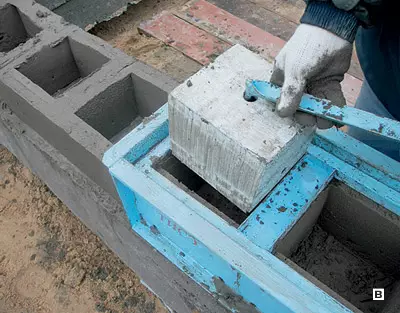
The TSE-2M module in our case was used for the inner walls of the house, tees-3m for external bearing walls with a falling insulation. Wall blocks were molded in the following sequence: the shape was installed in the form, they were fixed, then a mixture was filmed in 1-2 receptions and tamped it. The platform (removal of the form from the molded block) was carried out immediately after the mixture seal. One block was created in 4-7 minutes. For the implementation of the platform, all locking pins were removed and carefully removed the form. The planes of the angular blocks were carefully seen vertically and horizontally using a plumb and level. For the manufacture of inferticable blocks into the form, a hollow-formator and a scraper partition were laid.
Walling
The molding of the wall block is performed in the wall without a underlying solution, and it is possible to start the blocking of the blocks the day after the fill of the wrought. We want to emphasize that no waterproofing layer is not necessary to lay out between the first number of blocks and paintwork, since the fragmentation of moisture prevents the layer of parchment between the heads and the ends of the supports. Based on the length of the modules (510 mm) and, taking into account the inter-block gaps (about 10 mm), the length of the wall is recommended to do a multiple of 260mm (510: 2 + 10).It should also be noted that the smooth walls of the module of the stop-up formwork of tees allow the walls with a smooth surface that does not require the subsequent application of the plastering layer. This creates additional savings on materials, reduces labor and financial costs. You can erect such walls on any foundations.
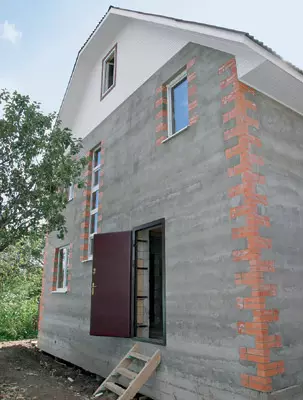
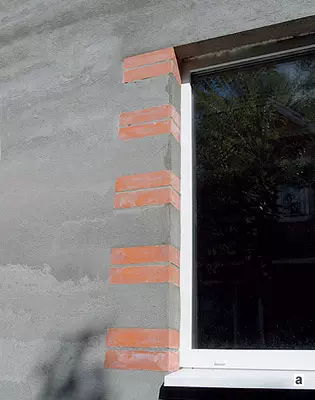
Before the start of the manufacture of the first row blocks, the cord was pulled. Focusing on it, installed the form. The outer walls were built using the TSE-3M module. The construction began with the masonry of the angular fragments of the wall (for an angular dressing) of three standard ceramic bricks, one of which was broken by half. The angular dressing can be performed and using a shorten wall block with a length of 12 cm, but in our case they chose a "brick" option as more decorative.
To create the next wall block, the module form set close to the newly completed block. At the same time, the hollow-formers were fixed in the form so that a thicker wall (11cm) was obtained from the inside of the house, and with outdoor-thin (9cm). When performing blocks of external walls for transverse reinforcement, basalt rods were used (the so-called "flexible communications", the cost of 1 piece-7rub.), Laid by one for each block.
After spending a mixture of one bag of cement (8-12 blocks), before it sets it, it has begun to align and smoke the side surface of the wall, for which it was used. Vertical gaps between blocks, holes from transverse pins, irregularities in horizontal seams of masonry were filled with a cement-sandy mixture of the same composition. The apack is not particularly thorough grout and the complete filling of the holes is not required, they were only covered (at a depth of no more than 1 cm).
To mount the wooden floors in blocks, a niche was made under the placement of the ends of the wooden beams with a cross section of 15050mm installed on the edge. The beams of the ground overlap were based directly to Ruralsk. The supports of the beams have placed in the pairing of adjacent blocks with a step of 520mm (multiple 260mm). To create a niche when executing the block, it is necessary to provide an additional hollow-formator. For the sake of this, a removable wooden liner with a height of 200 and 50mm thick, and its length was picked up, based on the block size (110mm for external and 45mm for the inner walls). When platforming, the liner was reversed. The next day, after laying a number with openings under the overlap, the beams themselves were installed, and then the formation of a new number of blocks was launched. Also arrived at the device overlap between floors. Dressing with the inner walls was not carried out, the internal and outer walls were erected independently of each other. If the space for the final block was less than its standard size, such an element was molded using a special formwork-compensator. If it was necessary to put the block between the other, created earlier, then the longitudinal pin did not insert into the hollows (otherwise it could not be removed from the form during the platform).
The straightness of the wall was provided by the manufacture of blocks on the cord. The vertical structure was tested every 4 row of masonry. If the wall "went away" to the side, the surface of the masonry was rubbed by Halfury so that the form set to it accepted the required position. The horizontal of the upper plane of each molded range of blocks was checked using a level. If necessary, it was also rubbed. The length of the sixter for side walls is not less than 50 cm, for the upper plane is not less than 120 cm, width is 10-15 cm. (In the future, it should be borne in mind that the holes for the bracket cannot be drilled in the joints of the blocks.)
Exterior walls must have high heat insulating characteristics. This can be secured by reliable insulation. The circuit with a flowing insulation was applied in the case: inside each block, a warm layer of foamizol was created with a thickness of 18cm. Such a design on the heat-saving characteristics is equivalent to a brick masonry with a thickness of 3m. The filling of foamizol with simultaneous seal was also performed every 4 row of masonry, after checking the verticality and horizontal wall.
Working mixture
Everyone who got acquainted with tees technology was interested in the composition of the concrete mix. Many have discarded doubts: is it really possible to define a block withsting after hardening the load of more than 100 tons after solidification? The whole secret lies in the bulk composition of the mixture consisting of cement M400, sand and water. The ratio of components of cement-sand-water: 1: 3: 0.5.
Sand Must be not small (dust), without clay impurities. If there will be many different fractions to 3mm in size in its composition, the full concrete mixture may turn out at a volume ratio of 1: 4: 0.5. When drafting the mixture, the cement brand should be taken into account. So, with a brand 500, its number can be reduced by 20%, but during the brand 300 will have to increase by 20%.
Number of water . Since the mixture should turn out to be tough, the amount of water added to it should be taken extremely carefully. With an excess of moisture, the molded block "floats" will acquire a barrel-shaped form, and with a shortage it will crumble after the platform. It should be noted that it is necessary to take into account the natural humidity of the sand, which has been in the open air for a long time: after the rain, the dosage on water can grow significantly. Nevertheless, experience shows that there are no problems with determining the amount of water - everything becomes clear on the first two or three blocks. Obviously, it is impossible to form blocks under heavy rain.
The mixture was as follows. At first, about half of the required sand volume were poured and scattered, then the cement bag was poured onto it, and the past part of the sand was poured. The whole mixture was stirred by a shovel before acquiring a uniform gray (without the yellowness of the sand). After that, from the resulting dry composition made a slide with a deepening in the middle, where the entire volume of water was poured. After 1-2 minutes, when the water was absorbed, the mixture was again shone, averaging viscosity. The preparation time of a mixture of one cement bag (50kg) was 8-10 minutes. The cement bag accounted for 12 buckets (10l) sand and 25l water. The mixture should be prepared as needed, given the speed of molding blocks. It is not necessary to store the product of the future, it is required to be used until the setting that occurs in 30-50 minutes. One cement bag is evenly spent when working with one module for half an hour. The volume of the mixture cooked from one cement bag is enough for 12 TIS-2M blocks or 8 TIS-3M blocks.
So that the outer walls are obtained sufficiently strong, they are every 4 row of masonry, immediately after frustration and tamping the insulation, reinforced with a special fiberglass grid. She does not create cold bridges, eliminates the drawdown of a bulk insulation and is easily rebated by ordinary scissors. Particularly watched so that the joints of the grids in the wall were located vertically on the same line and did not occur on the corners, window and doorways.
Molding a layer of blocks forming a door or window opening immediately after completion of the angular elements of this layer. Blocks near the opening themselves were made with such a calculation so that almost always inevitable incompletely-dimensional elements were located somewhere in the middle of the wall. The row under the window opening was laid on the reinforcement grid (to strengthen the design in the opening zone and drown out the horizontal channel of the wall). The resulting cavity was falling asleep with insulation, then stuck with pergamin, and on top were covered with a thin layer of solution. The gap between the inner and outer walls on the side of the window was covered with a board. For guard angles of openings, the laying was not adjusted to half the block, leaving the proceed under the support for the jumper. The block cavity on which the jumper will occur, filled with concrete. The jumpers above the window and doorways were performed by the traditional method of reinforced concrete elements in the formwork directly on the wall (concrete, the same as when pouring the screened). The dimensions of the door and window openings were made by multiple 26cm (the height of the window- 1350mm, width - 1290, 2060, 770, 1540 mm; door height is 2100 mm, width - 890, 790, 1030 mm). When installing standard door and window boxes, compensating boards are installed in such openings. Fastening boxes to TISE blocks is carried out in the usual way.
The inner walls molded using the TSE-2M module. At the same time, the first row began with blocks adjacent to the external walls. The emptying agents of the inner wall block were fixed in such a way that it obtained two equal in the amount of cavity separated by the vertical transverse partition. To implement the architectural design, window openings were also separated by elements of brickwork. The inner walls of the house reinforced reinforcement rods - for each row, two rods with a diameter of 6mm were used, located horizontally. It made it possible to use vertical wall channels to lay in them engineering communications. As the blocks were mounted by layers (one layer per day), the construction of the walls of the house lasted two ends.
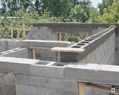
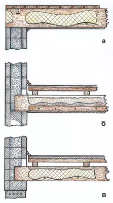
The rafters and roof farms were combined with walls through a sequence of 150150mm, close to the perimeter of the outer walls (Mauerlat). Maurylalat was fixed on the wall using mortgage elements made in the form of U-shaped lumps of wire with a diameter of 6mm. They were located around the perimeter of the wall in a step of 1.5 m and concreted into the block cavity. After the construction work, the installation of engineering communications has begun.
Overlapping
Between the beams of the lower overlap fastened the rotor of the rod 5mm with a pitch of 40cm. On topped the underfloor material, lay the insulation (Minvat 10 cm thick) and the same observed material. The lags (timber 55cm) were nailed over the beams with a step in 50 cm, and on their tight boards (32mm), Phaneur (6mm) and linoleum.
The floors in the bathroom were struck in the same way, instead of lag, pinned boards were fine (28mm). On top - another layer of boards under 45 to the beams of overlapping, shelled with polyethylene and was poured with concrete (30mm) with reinforcing the grid. After pouring the concrete on the glue lay a ceramic tile.
Kbalks between the first and second floor were nailed from the sides of the bars 44cm and hereinafter referred to as a black floor (20mm). Everyone was covered with polyethylene, on which sand hung (7cm). On top of the lags lay in 50 cm. The books were nailed with a tipped board (32mm), Phaneur and Linoleum. The first floor shortwater attached plasterboard (12mm).
The upper overlap was arranged similarly to the bottom, but after laying the insulation, the boards (28mmm) were knocked out.
Engineering Communication
In accordance with the adopted scheme in places of installation of the reinforcement (switches, outlets, IT.P.), during the molding of the blocks included the performance of the holes for it. In addition, wooden glasses were made, the sizes of which corresponded to the selected electric train. When creating a block in which a hole was assumed, a little solution was prevented, then the glass was placed in the formwork and the molding was completed. The glass was removed immediately after the platform. The regular box was fixed in place only after release from the opening of all wires involved in this node.
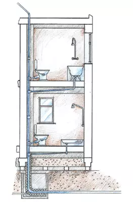
The injection of water pipes was carried out at a depth exceeding the estimated drainage depth of 0.5 m. At this level, the pipeline was under home and rose through underground. Under the building, in the communication zone of communications, there were veils from the reinforced concrete ring with a diameter of 1m. Extremely space pipelines were insulated with minvata.
Caliation and water supply risers are located behind a light partition in the bathroom. The partition was equipped with a sash for mounting and operation.
The riser of the sewer system was removed above the second floor with a ventilation pipeline with a diameter of 50mm. Ventilation is necessary for the proper operation of the septic and normal operation of water shutters on plumbing devices.
The gas supply system of the house was performed according to the open scheme, and not in intra-industrial cavities.
Exhaust ventilation channels were also performed on vertical inland walls. For each room created their own channel, the air ducts brought through the roof to the street. A room was provided in advance to a hole in the inner wall of the block, located in the upper row, for mounting the exhaust ventilation grid.
Supply ventilation was organized through special channels under the window frames. Before installing the window to the upper plane of the sub-wall, the connected ventilation tubes with a cross section 52cm (2 cm2 of the pipe cross section on 1m2 rooms) was laid.
Summing up, we note that, as follows from practical experience, tees technology provides:
reduction of total costs several times compared to other construction technologies;
the possibility of construction without the use of heavy lifting vehicles;
The possibility of construction at unprepared construction sites (without electricity).
The enlarged calculation of the cost of work and materials on the construction of the house with a total area of 155m2, similar to the represented
| Name of works | Unit. | Number of | Price, $ | Cost, $ |
|---|---|---|---|---|
| Foundation work | ||||
| Takes up axes, layout, development and recess | m3. | 17. | eighteen | 306. |
| The device of horizontal and lateral waterproofing | m2. | 39. | eight | 312. |
| The structure of the foundations of the columnar, monolithic reinforced concrete woods | m3. | 12 | 60. | 720. |
| TOTAL | 1340. | |||
| Applied materials on the section | ||||
| Cement | T. | 3.5 | 70. | 245. |
| Crushed stone granite, sand | m3. | 12 | 28. | 336. |
| Bituminous polymer mastic, hydrohotelloisol | m2. | 100 | 3. | 300. |
| Armature, knitting wire, sawn timber, etc. | set | one | 170. | 170. |
| TOTAL | 1050. | |||
| Walls, partitions, overlap | ||||
| Preparation of concrete mortar in the construction conditions | m3. | 78. | fifteen | 1170. |
| Laying of walls and partitions (TISE technology) | m3. | 76. | 75. | 5700. |
| Wall plastering mesh | m2. | 100 | 2.8. | 280. |
| Pouring jumpers of openings | rm. M. | 23. | sixteen | 368. |
| Alignment of the surfaces of the walls and partitions | m2. | 290. | 1,8. | 522. |
| Installation and dismantling of scaffolding | m2. | 78. | 3,4. | 265. |
| Device overlaps on stone walls | m2. | 155. | 12 | 1860. |
| Insulation of coatings and overlaps insulation | m2. | 260. | 2. | 520. |
| Filling the openings by window blocks | m2. | 23. | 35. | 805. |
| TOTAL | 11490. | |||
| Applied materials on the section | ||||
| Cement | T. | twenty | 70. | 1400. |
| Sand | m3. | 44. | fifteen | 660. |
| Mesh plaster fiberglass | m2. | 100 | 0.5 | fifty |
| Basalt rods (flexible connections) | PC. | 2300. | 0.26. | 598. |
| Insulation | m3. | 32. | 40. | 1280. |
| Armature 6mm. | kg | 70. | 0.4. | 28. |
| Sawn timber | m3. | nine | 120. | 1080. |
| Plastic window blocks (two-chamber double-glazed windows) | m2. | 23. | 240. | 5520. |
| TOTAL | 10620. | |||
| Roofing device | ||||
| Installation of the rafter design | m2. | 105. | 10 | 1050. |
| The device of the calane vaporizolation | m2. | 105. | 3. | 315. |
| Metal coating device | m2. | 105. | 12 | 1260. |
| TOTAL | 2625. | |||
| Applied materials on the section | ||||
| Profiled metallic sheet | m2. | 105. | 12 | 1260. |
| Sawn timber | m3. | four | 120. | 480. |
| Steam, wind and waterproof films | m2. | 105. | 2. | 210. |
| TOTAL | 1950. | |||
| Total cost of work | 15460. | |||
| Total cost of materials | 13620. | |||
| TOTAL | 29080. |